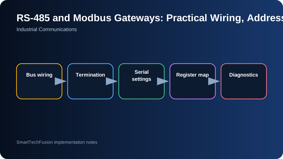
Separate RS-485 from Modbus
RS-485 defines the electrical signalling method; Modbus RTU defines a message protocol that often runs over it. A device can have correct A/B wiring but wrong Modbus settings, or valid register settings but a noisy electrical bus. Troubleshooting is faster when these layers are tested separately instead of changing every parameter at once.
Begin with a written interface sheet for each device: supply voltage, terminal names, isolated or non-isolated port, baud rate, parity, stop bits, slave address, function codes, register ranges, byte order, and scaling. Vendor labels such as D+, D−, A, B, 485+, and 485− are not always consistent, so use the manual and a controlled bench test rather than assuming label polarity.
Build a bus, not a collection of star branches
A conventional RS-485 network is a daisy-chain trunk with short device stubs. Long star branches create reflections and make behavior dependent on cable length and baud rate. Use a twisted pair for the differential signal and follow the device vendor’s grounding or shield recommendation. Keep high-current motor and relay wiring away from the communication pair where practical.
If the system includes equipment at different ground potentials, isolation becomes more important than convenience. An isolated gateway or repeater can reduce ground-loop risk. Do not join protective earth, cable shield, and signal reference indiscriminately; document where each is bonded and follow site electrical practice.
Use termination and biasing deliberately
Termination is normally placed at the two physical ends of the trunk, not at every device. Its value should match the cable impedance, commonly around 120 ohms, but the exact arrangement must follow the transceivers and equipment manuals. Too many terminators load the bus; no termination on a long or fast bus can produce reflections.
Bias resistors establish a known idle state when no driver is active. Some gateways include switchable bias and termination, while some devices include fixed networks. Count what is already present before adding external parts. On a short bench cable the bus may work without careful termination, which is why a bench success does not prove that a long field cable is correct.
Match serial parameters and addresses exactly
All devices on one RTU segment must share baud rate, parity, data bits, and stop bits, while each slave normally needs a unique address. Record changes immediately. A duplicated address can look like random corruption because two devices may answer the same request. A wrong parity setting can look like a dead device even when the electrical waveform is present.
Test one slave at a time before connecting the full network. Use a known-good USB-to-RS-485 adapter or gateway and a Modbus test client. Read a small, documented register first. This “one device, one request, one value” method provides a stable reference before polling multiple devices or adding application logic.
Interpret register maps carefully
Documentation may label the same location as 40001, holding register 1, or protocol address 0 depending on convention. Determine whether the software expects zero-based or one-based addressing. Confirm whether values are 16-bit integers, signed values, floating point, BCD, bit fields, or multi-register counters.
For 32-bit values, test word order as well as byte order. Scaling is equally important: a register value of 253 may mean 25.3 °C, 253 litres, or an invalid code. Preserve raw values during commissioning so a scaling mistake can be separated from a communication mistake.
Poll at a rate the network can sustain
A serial bus is shared. Calculate how many requests are sent, how long each response can take, and how retries affect the cycle. Polling dozens of registers from many devices every 100 ms can overload a modest baud rate. Group contiguous registers where the device allows it, and use slower intervals for values that change slowly.
Classify failures. A timeout, CRC error, exception response, stale value, and impossible engineering value are not the same problem. Log the slave address, function, register, timestamp, retry count, and error category. That evidence is much more useful than a generic “communication failed” message.
Commission with layered evidence
A strong commissioning sequence is: verify power, verify A/B polarity, verify idle voltage, read one register, validate raw value, apply scaling, connect the next device, then enable application polling. If problems appear after adding a device, return to the last working configuration rather than changing unrelated software.
Provide the client with a final topology diagram, device-address table, serial settings, register list, scaling rules, termination locations, and test captures. Remote support becomes much faster when both sides can refer to the same physical and protocol map.