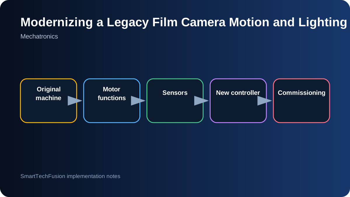
Document the machine before removing anything
Legacy machines often contain undocumented wiring changes and mechanical adjustments made over decades. Photograph every connector, label every wire, record motor nameplates, measure supply voltages, and draw the operating sequence before disconnecting a controller. Preserve the original parts until the replacement system is accepted.
Create a function map rather than a component list. Identify which motor advances film, which controls the shutter or pressure plate, which pair must move together, which sensor confirms position, and what the operator expects at each step. This reveals interlocks that are not obvious from individual wires.
Characterize each motor and load
Record motor type, winding or armature resistance, rated voltage, gearbox ratio, shaft arrangement, direction, speed, and mechanical load. A stepper requires a current-controlled driver and motion profile; a brushed DC gearmotor needs polarity control, current capacity, and position or timing feedback. Similar-looking motors may serve very different functions.
Test disconnected motors at conservative limits where safe, but do not assume free-running behavior represents the installed load. Film tension, rollers, pressure mechanisms, and take-up inertia can change current and required acceleration. Measure movement and current on the real mechanism with protective limits.
Treat paired motion as a synchronization problem
If two motors must advance film together, simply applying power at the same time may not keep tension balanced. Determine whether one motor meters the film while the other maintains take-up tension. The control strategy may need a master movement and a torque- or speed-limited follower rather than identical commands.
Add a controlled start and stop profile to avoid shock. Monitor for a jam, missing rotation, or excessive current. Provide a manual jog mode at low speed so film can be loaded and recovered without running the full automatic sequence.
Decode sensors with evidence
For a multi-pin legacy sensor, identify supply, ground, outputs, and shielding from documentation or measured behavior. Use a current-limited bench supply and an oscilloscope or meter. Record sensor state at known mechanical positions. Do not connect an unknown signal directly to a new microcontroller.
Interface circuits may require level shifting, pull-ups, filtering, or isolation. Preserve raw input diagnostics in the controller so commissioning staff can see each sensor change. A named status such as “pressure plate closed” should be traceable to a physical input and expected voltage.
Separate motion, exposure, and operator interface
Use a controller architecture where the motion sequence, lighting or exposure control, and user interface are modular. The sequence controller owns interlocks and timing. The UI sends high-level requests and displays states. The exposure module drives the RGBW source with calibrated limits rather than allowing arbitrary channel commands from the screen.
Include states for idle, loading, ready, moving, exposing, completing, and fault. Every state should define allowed transitions and safe outputs. If a sensor does not confirm movement within a timeout, stop energy to the mechanism and present a recovery instruction.
Preserve manual recovery and emergency stop behavior
A modernization project should improve recovery, not hide it. Provide accessible jog controls, release procedures, position indicators, and a way to remove film safely after a fault. Emergency stop should remove hazardous motion energy while preserving enough control power to report the state where appropriate.
Document which outputs are de-energized, how a restart is authorized, and whether the sequence resumes or returns to a known position. These decisions belong in the control design, not as an afterthought in the user manual.
Commission one function at a time
Test inputs first, then individual outputs, then unloaded movement, loaded movement, paired motion, exposure, and finally the complete cycle. Keep acceptance records for direction, speed, current, position confirmation, repeatability, emergency stop, recovery, and final image or film handling quality.
Deliver schematics, I/O list, motor settings, source code, controller backup, wiring labels, service notes, and a change log from the original system. A successful retrofit preserves the machine’s useful behavior while making every new dependency understandable.