Measure the real switch motion
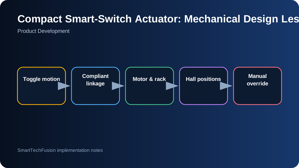
A wall toggle does not move as a simple vertical slider. Its tip follows an arc around the switch pivot, and different plates expose different lengths. Measure the required force, angular travel, tip path, plate dimensions, and clearance around the wall. A CAD model based on a guessed straight stroke will bind or push sideways.
Capture several representative switches if the product is intended to be adjustable. Define the supported range rather than claiming universal fit. The mechanism should allow alignment in height, lateral position, and travel while remaining rigid after installation.
Use compliance at the contact point
A hard fork around the toggle can jam when the arc and slider path differ. Add a compliant interface: a rounded slot, spring element, pivoting link, flexible pad, or controlled clearance. Compliance absorbs small alignment error while the main housing carries the motor reaction force.
The contact must work in both directions without slipping off. Test slow manual movement with the motor unpowered to observe side load and interference. Wear surfaces should be replaceable or robust enough for repeated operation. Avoid sharp geometry that concentrates stress on the switch.
Size the motor from force and geometry
Measure switch force at the contact point, then calculate required rack force and motor torque with margin for friction, battery voltage, and printed tolerances. Stall current matters because it affects the driver, battery, wiring, and thermal behavior. Do not use stall as the normal end-stop strategy unless the system is designed and tested for it.
A gearmotor gives torque but may be slow and hard to back-drive. The gear ratio should meet acceptable movement time while preserving manual operation. If the mechanism cannot be manually moved, provide a clutch, release, or linkage that does not lock the original switch during a power failure.
Guide the rack without excessive play
A compact printed rack needs enough bearing length to resist rotation. Short guides can allow the rack to tilt, making the fork misalign with the toggle. Use two separated guide surfaces or a captured channel, and specify clearances for the intended printer and material.
Print orientation changes strength and dimensional accuracy. Add chamfers, lead-ins, and accessible fasteners. Test the mechanism with intentionally varied print dimensions to understand the tolerance window rather than fitting one perfect prototype only.
Use position sensing for normal stopping
Hall sensors and a small magnet can represent OFF, centre or manual, and ON positions without mechanical contact. Place the magnet pocket and sensor locations so the field changes are distinct across the full tolerance range. Read raw sensor values during setup and store calibrated thresholds if necessary.
Position sensing should be combined with a movement timeout and current monitoring where available. If the target position is not reached, stop the motor and report a fault. This protects against a blocked toggle, depleted battery, detached housing, or damaged rack.
Design manual control and electronics together
The user should still understand and operate the physical switch. Define what happens when a person moves it while the actuator is idle or moving. Firmware should reconcile sensor state with commanded state instead of assuming every motor command succeeded.
Battery life depends on standby current, BLE advertising, motor events, and charger losses. A few motor operations may use less energy than an always-awake radio. Measure sleep current on the assembled board and include battery protection, safe charging, and a clear low-battery behavior.
Test installation, not only bench motion
Mount the device on real wall plates with adhesive or the intended fixture. Test repeated ON/OFF cycles, manual overrides, stiff switches, slight misalignment, temperature changes, low battery, and obstruction. Observe whether the housing lifts, twists, or transfers load to the plate.
Freeze the architecture only after the mechanical envelope, travel, sensing, manual behavior, and print process have passed a defined test. The final package should include STEP/STL files, assembly drawing, tolerance notes, BOM, wiring, firmware, calibration, and a short motion demonstration.