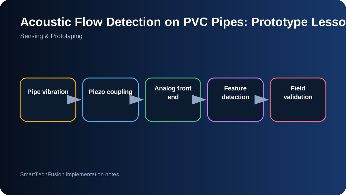
Keep the first claim narrow
A prototype should first answer a binary question such as “is there a repeatable acoustic change when water is flowing at this installation point?” It should not immediately claim flow rate, leak location, or universal performance across pipe materials. Narrow claims make testing honest and help identify which physical effects are actually measurable.
Water-flow sound depends on pipe diameter, wall thickness, supports, bends, fittings, surrounding structures, flow regime, and background machinery. A result on a short bench pipe is evidence for that setup, not proof for a sixty-metre drain. The field plan must deliberately vary these conditions.
Make mechanical coupling repeatable
Piezo sensors respond strongly to how they are pressed against the pipe. Use a defined clamp, pad, adhesive layer, or housing so contact force and position can be reproduced. Mark the pipe and sensor orientation during tests. Loose coupling can create larger variation than the water event itself.
Test several placements: straight section, near a bend, near a support, upstream, and downstream. Avoid assuming the physically closest point is always best. Fittings and supports may transmit or attenuate particular frequencies. Record photos and dimensions so promising locations can be repeated.
Protect and characterize the analog input
A piezo element can generate high transient voltage. Use appropriate biasing, current limiting, clamping, and an amplifier designed for the expected signal range. Confirm that the ADC never sees voltage outside its allowed limits. A circuit that survives gentle taps may still be overstressed by a sharp impact.
Capture raw waveforms during development. Measure baseline noise, transient peaks, saturation, settling time, and frequency content under no-flow, flow, pump, impact, and handling conditions. An LED that switches on is useful for demonstration but cannot explain why the detector triggered.
Use features more stable than one ADC threshold
A single instantaneous threshold is sensitive to impact and electrical noise. Consider windowed features such as root-mean-square amplitude, peak count, band energy, zero-crossing behavior, or the difference from a learned baseline. The best feature is the simplest one that separates the tested conditions consistently.
Add debounce and persistence. For example, require elevated energy in several consecutive windows before declaring flow and several quiet windows before clearing. Log the feature value and state transition. This produces a detector that can be tuned from evidence rather than from a hidden constant.
Build a test matrix before changing the algorithm
Test no-flow and flow at multiple rates, pipe sizes, sensor positions, coupling pressures, times of day, and background-noise conditions. Include knocks, footsteps, pumps, valves, and nearby vehicle movement as negative or confounding events. Randomize the order where possible so expectations do not influence the result.
For a long drain, test progressively at known distances and pipe sections. Compare the local sensor response with the event time at the source. If a separate beacon is used, record its drive level, mounting, distance, and detection margin. A long pipe may transmit some frequencies better than others, so test patterns should be controlled.
Separate sensor detection from communication
First prove the sensor can classify the event locally. Then connect LoRa, Wi-Fi, or another notification path. Otherwise a missed message may be mistaken for a missed acoustic event. Keep counters for sampled events, detected events, and successfully delivered notifications.
When the use case requires immediate notification, define acceptable delay and retry behavior. Preserve a local timestamped event log so connectivity failures do not erase evidence. A gateway cannot improve a sensor that is mechanically inconsistent, and a good sensor should not be judged by an untested network path.
Define acceptance around the installation class
A practical acceptance test might specify a particular pipe material and diameter, mounting method, distance range, minimum flow condition, maximum false-trigger rate during a defined observation period, and environmental limits. This is more defensible than saying the device works on “all drains.”
Document the installation procedure, baseline collection, threshold or model version, test results, known interferers, and maintenance checks. The strongest outcome of a prototype is not a dramatic signal; it is a repeatable method for deciding where the approach works and where it does not.